Introduction
It is therefore inevitable to give proper attention in a reasoned and scientific determination of the requirements of buildings in respect of thermal, audio and visual comfort, and how these can be best achieved practically and economically, under various conditions. Elaborated studies on visual, thermal, indoors wind pattern and acoustical environment under different design parameters in various prevailing climatic conditions has been done on in the Central Building Research Institute, Roorkee (India). The economic feasible solutions have also been incorporated in National Building Codes/ Codes for building practices from time to time. Various reasons worldwide have been advocated for need of presence of sunlight indoors but in tropical climate its presence for most of the time is undesirable. The technological advancement is capable of modifying the environmental quality of a habitat to a greater extent by using artificial heating/cooling devices to a greater extent, yet the impact of solar effect is an important aspect of architecture, inevitable in any climate, regardless of weather be it moderate or tropical. Which if ignored in the design of buildings and planning of layouts may lead to uneconomical building indoors.
Present Approach
In recent architectural development the use of large expanses of glass has increased manifolds. In developing countries and on tropical belt, as India, solar radiations add heat and glare to a discomfort level support further to the significance of bringing under control impact of solar radiations. Which contribute enormous heat indoors due to overheated period during summer season. The most effective means of solar radiation through glazed area, by far the greatest source of heat ingress is to block the direct sunrays before they can enter. It is quite obvious that window glasses are practically transparent for short-wave radiation emitted by the sun but almost opaque for long-wave radiation emitted by objects in indoors. The consequence of this is that the radiant heat, once it has entered through the glazed area, is tapped inside the building. This could, in fact increase at times the indoor temperature far above outdoor air temperature, even in moderate climates 'greenhouse effect'. An ordinary window glass transmits a large proportion of all radiation between 300 and 3000 nm.i.e. Both visible light and short-wave infra-red, but very little around and outside these values. With the recent advancement in glass technology, it is possible that varying the composition of the glass to reduce substantially the infrared transmission and modify this selective transmittance of the ordinary glass. But it would only slightly affect the light transmission (Heat absorbing glass). But uneconomical when large glazed area is provided. It occurs too frequently that the extent and seriousness of direct sunlight penetration is virtually only fully realized after the building is completed and occupied, so that the means of sun control is left primarily, or even entirely, to the devices on the inside of windows, such as curtains and Venetian blinds. But these are not very effective ways of sun control. Though they stop the passage of incoming radiation but absorb solar heat. This will be partly convected to the indoor air results increase in indoor temperature and partly reradiated. Half of this re-radiation is outwards, but as it is of long wavelength it is not transmitted through the window glass. The usual narrow space between the window and the blind will thus be quite substantially overheated. Given the means for accurately plotting the sunlight and shade patterns in and around buildings much can be done in the planning and design stages to affect a degree of control which will either eliminate the need of internal screening and blinds, or minimize their use. The factors which enter into the problem are the sitting, orientation and general arrangement of occupancy inside building; the positioning of the openings in external walls and the depth of the reveals, the placing of the structural projections (balconies, canopies, overhangs, sun-break walls, etc.). By careful analysis of the sun's orientation at various times of the day and year, normally provided by solar path diagram, described subsequently, one is usually able from the very start of the design of a building, to introduce means for making proper use of sunlight where and when needed and for limiting its presence.
The use of external sun-breaker is no longer confined solely to houses, shops and factories but the current trend in architecture towards their application is a requisite on much elaborate and extensive scale, in large blocks of commercial buildings and multistorey flats. Where continuous strip-windows and air conditioning are to be incorporated in very large structures, permanent external shading devices, if scientifically designed, can be an acceptable and economical preposition. It will effect a substantial reduction in cooling loads resulting in worth-while saving in initial and operating costs of air-conditioning plant. Further, even where the cost of providing shade does appear initially to be high use of sun-control projections is justified because they make enough difference to comfort indoors. The proper design of sunlight and shades are also significant in site-development and town-planning. Where, the main emphasis should be on the mutual shadowing of buildings to ensure as far as possible to avoid permanent obstruction to the winter sun-light even to the lower floors of multi-storeyed buildings particularly in cold or composite climate. In town planning, the principle of taking due account of sunlight requirements of individual structures is of concern not only in deciding the spacing, shape and relative arrangement of building units, but receive attention in street lay-out and orientation, where the choice is not dictated by other relatively less important factors. Thus to ensure the best possible indoor environmental conditions, it is suggested to rely on structural controls to obviate the need for any mechanical controls and even if mechanical controls do have to be restored than the task will thereby be reduced to a minimum. Although the solar impact is a combined effect of direct and diffuse radiations but the later being very complex and to limit the extent of variables only the former is being considered. Unless a proper balance is achieved in the shape, size, grouping and orientation of the building blocks, the environmental quality of the habitat may be jeopardized.
Solar Chart
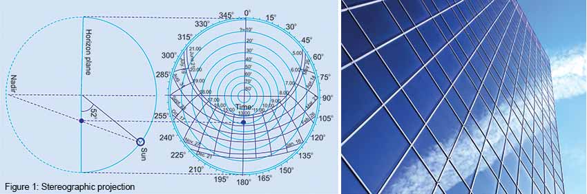
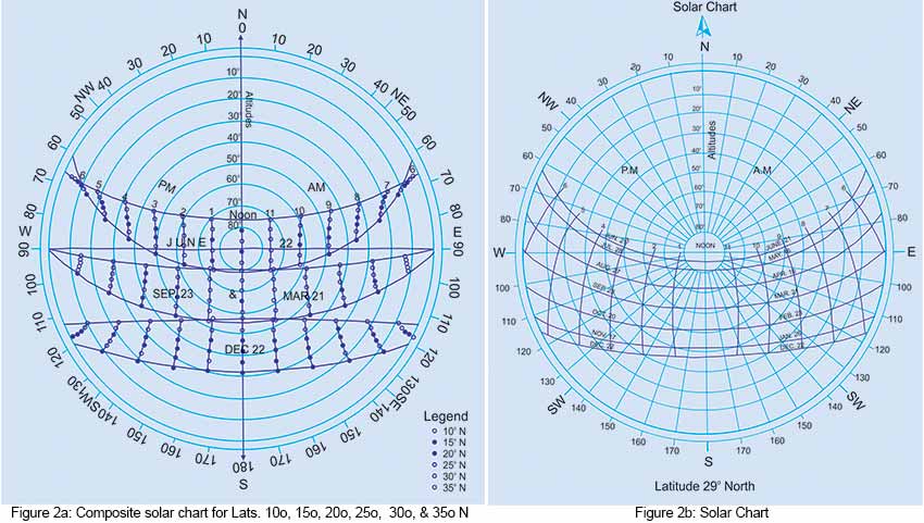
Protection of windows from solar radiation permanently one needs the angular position of sun’s position in relation to the wall surfaces of any orientation at various times of the year. It is necessary to calculate the intensity of solar radiation falling on a surface or an opening e.g and to judge shadows by surrounding obstructions e.g. buildings, trees, etc. to workout the design of fixed shading devices on openings during summer period. The solar chart is an aid described as the plane representation of the apparent solar path across the celestial sphere. The polar diagrams are so arranged in a form helpful to visualize fairly correctly the extent of the apparent daily sweep of the sun across the sky for various days and for different latitudes in the year. Therefore, before discussing the methods and their usage it is important for an observer to define the position in which one observes the sun expressed in terms of solar altitude and solar azimuth; the one fixing its height in the sky and the other corresponds to the angle on plane between true north and the sun’s line. It is possible to determine for all places covered by their representative latitudes, the time period during which a particular building or any other object will shade the site. Thus with the help of solar chart the entry of direct solar radiation through a window or sky light to a point inside the building can similarly be predicted by plotting the coordinates of the corner of the aperture on a solar chart. If a roof overhang or other exterior structure is visible through the window, its coordinates can be used for that portion of the aperture. The mathematical method is tedious involving a degree of precision and is also not required by architecture. However, the graphical procedures are simple in use and widely spread over. There are several methods of projection for representing the sun’s apparent movement two-dimensionally but the stereographic method of projection, as explained in Fig. 1 is by far the most commonly used. Hour-lines are marked in British Standard Time with Greenwich Mean Time would be 12.00. The various points of compass represent the various directions. The concentric circles, beginning with zero at the outer periphery and rising to 90 deg. at the center, represent the solar altitude. In the case of equidistant projection, the radial distance from the centre of the chart to the periphery is divided in to 90 equal divisions, each division representing a degree. It has a common character, that they are single latitude systems: each chart appropriate for single geographical latitude only. The basic idea is that earth is stable and the sun passes above the horizontal plane, on which its path is marked on some key dates having relation of standard time and solar altitudes. The observer is assumed at the centre of the polar diagram. The “nadir” point is taken as the centre of projection and the sun’s position on the apparent sky-hemisphere is projected onto the horizon plane represented by a horizontal circle (Fig.1). The selection of representative latitudes for a country is so selected as to cover most of the large urban areas lie very close to the latitude chosen. Furthermore, the greatest difference between any place and the selected latitude is so small that the errors involved in using the chart of nearest latitude are of little practical consequence. The mid-point of the chart and plane of the paper represent the position of the observer and the horizontal plane through this position respectively, while the heavy un-graduated circle with the mid point as centre defines the observer's horizon. From the angular graduations marked around the circumference of the outer circle, it is possible to read off any direction through the observers's position in terms of the points of the true compass, or as an angular distance east or west of true north. The sun's paths during the course of the day on selected dates are represented by a group of curved lines running from the easterly to the westerly horizons (the dates line), which are intersected by the short 'hour lines'. The radial line shows the solar azimuth and the series of concentric circles establish a scale of altitude angles. The upper and lower curves are for summer and winter solestics. The other curves are for two dates having the same declination angle of the sun. These path lines are crossed by hourly time lines refering to solar time. But in reality they have irregular contours corresponding to the boarders between countries. Actually time meridian also exists for areas between time zones, which are not arranged in a periodicity of whole hours. Thus every time zone is assigned with a meridian. This for Greenwich Mean Time (GMT) is 0 deg. and Central European Time is 15 deg. in which the true solar time coincides with the time zone. The intersection of the solar path for any date with any hour line represents the altitude and azimuth of the sun on that specific time and date. Sunrise and sunset are known by the intersection of the sun path curve with the outermost circle representing horizon. A line drawn through the sun's position and the mid-point of the chart will indicate the direction on plan of the sun's rays and hence the azimuth. The altitude of the sun above the horizon is given by the relative distance between the sun’s position and the mid-point as measured from the mid-point along the scale marked "solar altitude". The hour of sunrise and sunset can be determined from the relative position of the hour lines. It is significant to note that the reference point for the altitude scale is the mid-point of the chart and not the point corresponding to zero deg. on the scale. The solar altitude could be determined more easily by using the shadow-angle protractors, or alternatively, if a series of concentric circles are described above the mid-point of the chart in such a way that the circumference of a circle passes through each of the divisions marked on the altitude scale. These concentric circles have purposely not been drawn on the charts to avoid confusion, and also because solar altitudes are seldom required, it being more advantageous in analysis to use vertical shadow-angle. Since it is the sun's declination which determines the angles of the sun for any particular place and time of day, it is considered that the most convenient sun's path lines to show on the charts are those for which the declinations differ by some constant amount. Therefore, the path lines shown on chart are for the dates of the solstices and for the dates when the solar declinations are 0 deg., 5 deg., 10 deg., 15 deg., and 20 deg., north or south. Therefore, it is an easy matter to interpolate between lines so as to determine the sun’s position on any intermediate date. Precise accuracy in interpolation is not wanted, since it is generally of little significance whether a shadow or patch of sunlight falls on a predetermined area at a given hour on the exact date for which the designing was arranged, or whether this event occurs a day or so before or after that date. Times, indicated by the hour lines on the solar chart are apparent solar times,12 o’clock midday occurring when the altitude is greatest, the azimuth then being either zero or 180 deg. The apparent solar time for any place differs from the standard or clock time by an interval that varies from day to day and with the longitude of the locality. To maintain the general validity of the solar chart, the hour lines are not indicated with the time as shown in the clock. The statutory time of general interest to the country, which construe the regularity of life in a country on which one's planning is based, does not coincide with the true local solar time. The proper designation of the hour lines is determined by the difference between the time in the country (Standard time) and the local solar time. Hence, if one is interested in an examination of sun and its shade patterns at specific standard times, a conversion from standard to apparent time is necessary before making use of the solar charts. Most sunlight problems can, be studied on the basis of solar time only. But there are instances, such as the exclusion of sunlight from a working surface during normal working hours, when it may be particularly desirable to plan in terms of standard time. The existing "Solar Charts" presents an entirely new feature and should prove an easy and quick means for making sun studies of buildings in any part of the country and in any situations, using normal drawings of plan and elevation. The World Solar Chart presents an entirely new feature: it's multi-latitudinal. The notable advantage is that, instead of 180, only seven charts provide the necessary information. The single latitude charts are based upon the idea that the earth is stable and the sun passes above the horizon plane, on which its paths are marked on key dates with relation of standard time and solar altitudes. The notable advantage representing only a few selected charts for each alternate latitude, of the country has been published (Climatological and solar data 1969). A composite single solar chart covering wide spread of the whole country and one for only Latitude of 29 deg. N has been shown in( Fig. 2 a & b) respectively. It is found to be more convenient to the new approach opting for a multi-latitude system based on the globe spinning around its axis, declining and revolving along its orbit. A movement has been transformed into a few graphs. Owing to this, readings are considerably simplified and will be of value in the development of architectural activities in any part of the country. It serves to a reasonable accuracy required for designing purposes.
Shade Angle
Knowing the altitude and azimuth for any particular position of the sun one can, by means of its geometrical projections upon the drawings of a building, can determine the direction of approach of the sun's rays in elevation and in plan for any part of the building. But it is not very convenient for the designer to determine, from the sun's angles what areas in or about a building are exposed to direct solar radiation, particularly due to the fact that the solar altitude is measured in the direction of the sun. For calculating the intensity of solar radiation falling on a surface or an opening viz; window, it is necessary to find the angle of incidence of solar radiation associated with the position of the sun at various times of the year in respect of building elevation. The prediction about direction of the sun's beam would assist to judge shadows by neighbouring buildings, trees etc. for protection against solar ingress during summer period and also in estimating the dimensions of fixed shading devices on windows. Sun's position in the sky is essentially determined by its altitude and azimuth. These angles can be calculated by the knowledge of the various angles and using the trigonometric equations (Fig. 3). It could be easy to understand if the earth is imagine being stationary and as observer standing at some place on its surface and the ground about it looks as a circular plane of indefinite radius bounded by the horizon. Then conceive the sky as being some hemispherical shell completely covering the plane on which we stand. Then during the course of the day, sun will appear to follow along the arc of a circle, which is symmetrical about the vertical plane running north and south. At so-called solar noon, the sun lies in this vertical plane and occupies its highest position for the day. This motion of the sun is made apparent because of the earth revolving daily on its axis. Besides its daily movement, it is also affected by the second apparent motion, which we can only notice as day follows and the sun is seen to travel along slightly different but parallels each day. Thus during the period of a year, it would appear as if the sun slowly migrates to and fro between south and north points in the sky. This second motion is due to the annual movement of the earth about the sun, which in effect causes a relative shift of the sun to the south and to the north of the equator. The angular displacement of the sun from the plane of the earth's equator at any time is termed the declination of the sun. This angle changes continuously between a value of almost 23.5 deg. South at the time of winter solstice on the 21 or 22 December, to almost 23 .5 deg. North at the time of summer solstice on the 21 or 22 June. The latitudes at + and - 23.5 deg. the tropics of cancer and Capricorn, enclose the only region on the earth where solar insolation strikes normal to its surface at some time during the year. It is when the sun during a year, would appear to trace out with the longest and highest pattern of daily paths, corresponding to the day of summer solstice and the shortest and lowest to the day of winter solstice. Thus in India the shortest day of the year occurs in the northern hemisphere when the sun is vertically above the Tropic of Capricorn at latitudes 23 .5 deg, South. The intensity of direct radiation varies from a maximum value near the equator to minimum values near the poles according to cosine law. Because the axis of the earth's rotation is not parallel to its axis of revolution about the sun, the latter is vertically above the earth's equator only twice during the year viz; at the vernal and autumnal equinoxes. The summer and winter solstices correspond to the times when the sun is farthest from the earth's equator.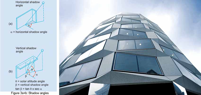
Shadow-angle Protractor
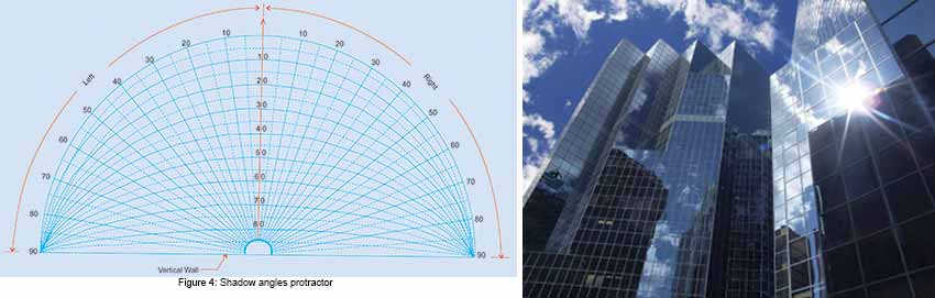
Sun-angles will rarely provide shadow angles directly, since these can be derived in special cases only, when the sun's azimuth is normal to the elevation. In order to determine the type and size of shading devices, a shadow angle protractor is used, otherwise calculation or geometrical projection would be too much time consuming. A shadow angle protractor is a semi-circular figure, (FIG.4) designer can draw on a transparent paper or celluloid sheet and the diameter of which is same as that of the solar chart in use. The base line of the semicircle represents a vertical wall, used to convert true solar altitudes into shadow angles. In other words, it provides a representation of the shadow angles on a horizontal plane in stereographic projection and to the same scale as the sun-path diagrams or solar charts but in which the base line represent a series of imaginary sun's path lines such that, if the sun would have follow along any one of them the resultant vertical shadow-angle remains unchanged. The graduations on the curved lines identify the vertical shadow-angle to which the curved lines correspond. The series of curved lines joining the two extremities of the base line and another of radial lines represent the vertical and horizontal shadow angles respectively. These are the angles between the sun and the normal to the wall surface. Every point within the semicircle therefore refers to some values of vertical and horizontal shadow angles. One can use by placing the shadow angle protractor with the centre of the protractor directly over the mid-point of the selected solar chart. The protractor is then turned about its centre until the base-line assumes the orientation of the vertical plane or surface which it is supposed to represent the direction of the wall having the window opening for which the louvers are to be determined. But the period during the year when sunlight entry is to be cut off, should be masked on the solar chart. Then try to find out by the method stated the vertical and horizontal shadow angle or a combination of both, which successfully mask off the undesirable region of the solar chart under consideration. This will occur when the centre-line of the protractor cuts the angular scale marked around the solar chart at the point corresponding to the desired aspect; e.g. if the vertical surface faces north-east then the centre-line of the protractor should point to the division marking north-east ( i.e. 45 deg. east of north ) on the angular scale around the solar chart. The appropriate vertical shadow-angle for any position of the sun previously located on the chart can now be read off on the curved line scale of the protractor. At the same time, the horizontal shadow-angle can be determined from the point at which a line through the protractor' centre and the sun position on the chart cuts the graduated scale around the circumference of the protractor. To ascertain these angles without having actually drawn any lines on the solar chart, radial lines at 5 deg. intervals are included in the protractor. The significant point worth noting about the protractor is that the scale of vertical shadow-angle of the centre-line of the protractor coincides exactly with the scale of the solar altitudes on the charts. Thus, the protractor can be used to read off solar altitudes from the solar charts.
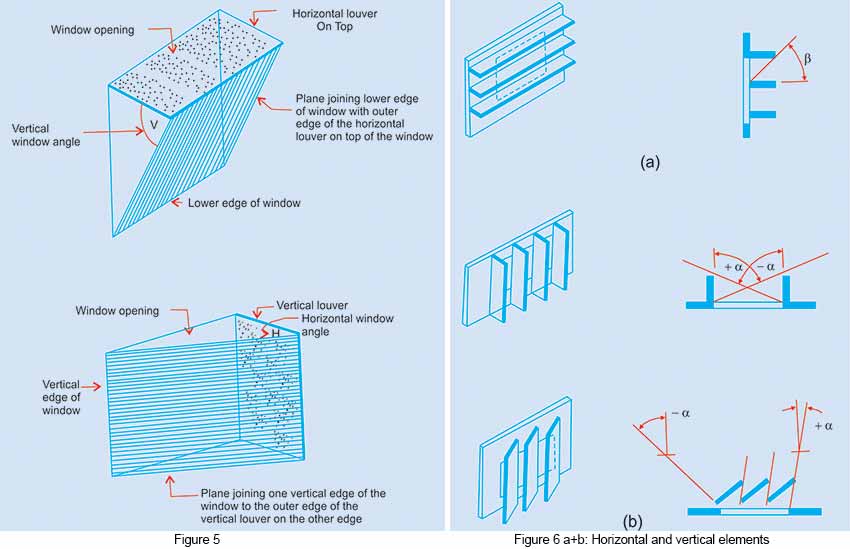
To expedite the process of sun light and shade analysis, it is much more convenient to make use of the so-called horizontal and vertical window angles (Fig.5). The angle with the horizontal plane subtended by the plane joining the outer edge of a horizontal louver on the top of the window to the lower edge of the window is called the vertical window angle. For a given window height, this angle indicates the size of the horizontal louver on the top of the window. The sun is masked from entering the window by a horizontal louver for all regions of the sky which have a vertical angle larger than the vertical window angle masked sky region by hatched area (Fig.6 and Fig.7 a & b). Similarly, the angle subtended by the plane joining the outer edge of a vertical louver on one side edge of the window to the other vertical edge of the window, with a vertical plane normal to the window, is called the horizontal window angle. For a given window width this angle represents the size of the vertical louver on one side edge of the window. The sun is masked by the vertical louver from entering the window as long as the horizontal shadow angle of the sun is greater than the horizontal window angle. The masked region due to left side and right side vertical louver on the shadow angle protractor (Fig. 8 a & b) and due to both vertical louvers is as shown in Fig. 8 c. respectively.
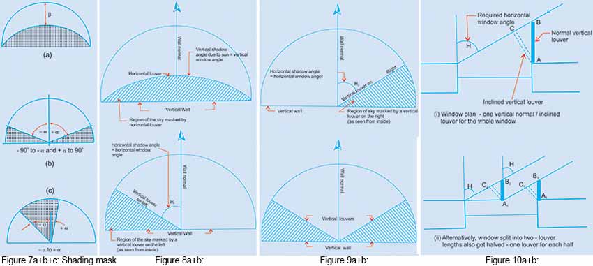
But in literature the most common terms Horizontal and vertical shadow angles are used (Fig. 3). Which are measured from a line perpendicular to the elevation, and indicate the limit beyond which the sun would be excluded and within which the sun would reach the point under consideration. A horizontal shadow angle (Fig.3 a) is the difference between the solar azimuth and wall azimuth, same as the horizontal component for the angle of incidence and is a measure of the performance of vertical shading devices, consisting of louver blades or projecting fins in a vertical position. Narrow blades with close spacing may give the same shadow angle as broader blades with wider spacing. Whereas the Vertical shadow angle characterizes a horizontal shading device it is a long horizontal projection from the wall measured on a vertical plane normal to the elevation considered (Fig.3 b). The distinction between solar altitude angle and the vertical shadow angle is that first describes the sun position in relation to the horizon whereas the second describes the performance of a shading device. Numerically both the angles will coincide only when the sun is exactly opposite the wall considered. But when the sun is sideways from the perpendicular, the vertical shadow angle is always larger than the solar altitude angle. The protractor gives a representation of these shadow angles on a horizontal plane in stereographic projection. The devices can also be estimated using Vertical window angle expressed as the angle subtended with the horizontal plane, by the plane joining the outer edge of a horizontal louver on the top of a window to the lower edge of the window and measured on a vertical plane normal to the elevation considered. For a given window height, this angle indicates the size of the horizontal shading devices i.e. a long horizontal projection on the top of the window (Fig. 3 a). For calculation of depth of insolation those components of the sun's rays that are in normal plane to the elevation, also vertical shadow angles are required. The sun is masked from entering the window for all regions of the sky, which have a vertical shadow angle larger than the vertical shadow angle. On the shadow angle protractor the masked region of the sky is indicated by the hatched area (Fig.7 & 8). A horizontal shading device will be most effective when the sun is opposite to the building face considered and at a high angle, such as for north and south facing walls. To exclude a low angle sun, this type of horizontal shading would have to cover a window completely, permitting a downward view only. Similarly the angle subtended by the plane joining the outer edge of the vertical louver on one side edge of the window to the other vertical edge of the window, with a vertical plane normal to the window, is called the horizontal shadow angle H. For a specific window width this angle represents the size of the vertical louver on one side edge of the window (Fig.6). It gives the difference between the solar azimuth and wall azimuth. The horizontal shadow angle measures their performance. Using the shadow angle protractor, the shading portion of a given device can be established (Fig. 8) and if done on the scale similar to protractor on tracing paper, it can be laid over the appropriate solar chart. It would help in providing the shading time along-with dates and hours for a particular device. It is very quick shortcut to do away with the need to establish solar position angles. The sun is masked by the vertical louver from entering the window as long as the horizontal shadow angle of the sun's position is greater than the horizontal window angle (Fig.9). This type of device is most effective when the sun is to one side of the elevation, such as an eastern or western elevation or the sun is opposite to the wall considered. While designing, the hot period during the year when sun-light is to be cut-off should be marked first on the solar chart. Then in an endeavour is to find the vertical or horizontal louver or a combination of both i.e egg-crate type (Fig.10.) to mask-off the undesirable hot region. Many types of grill-blocks and decorative screens may fall into egg-crate type. The method of constructing the shading mask for a moderately complex shape as egg-crate type can be effective for any orientation. Once the requisite horizontal or vertical shadow angles (Fig. 3) or Window angle (Fig.5) are determined, it is simple to find-out the size of the louver. AB line represents the resulting vertical louver normal to the wall (Fig.9). It can also be replaced by an inclined louver AC without any effect on the masking angle of AB. The purpose of inclining the vertical or horizontal member is always to reduce the outward projection of an unwieldy louver system. Inclined louvers, apart from being un-economical, are resorted to only for economy of space and material consideration although they restrict outside view and daylight along-with influencing the wind flow pattern indoors. Therefore, if an alternative is available, the angle of inclination beyond 30 deg. should possible be avoided. Whenever a vertical louver is inclined in any direction away from the normal, the extreme member at the edge of the window, in the direction of inclining, does not serve any useful purpose and can be avoided (Fig.9) Similarly, with knowledge of the desired window angle, the size of the horizontal louver on top of the window or an equivalent inclined louver can also be determined.
References
- Hopkinson, R.G., Architectural Physics, HMSO, 1963
- Maitreya, V.K., "A rational approach to Air-Conditioning Load estimation," Publication: New Building Material & Construction Works, Vol. 11, No.6, (2005)
- Olgyay, V and Olgyay A, "A solar control and shading devices," Princeton University Press, 1957
- Sunlight in Buildings: Proc. CIE Conference, Rotterdam, (1967)


