Prof. D.S.R. Murty, Professor of Civil Engg. Andhra University, Visakhapatnam, S.V.N. Suryanarayana Raju, Senior Structural Engineer, D.V. Trinadha Rao, Junior Engineer, Vijay Nirman Co Pvt. Ltd
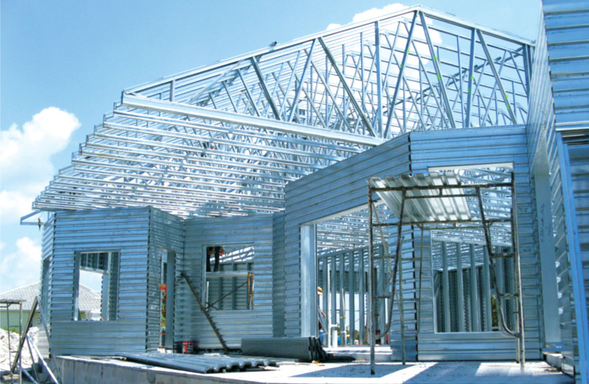
Currently the sustained efforts of designers, manufacturers of materials and builders to innovate and incorporate unmatched excellence in the construction of roof trusses of large areas have resulted in highly functional, economical and pleasing structures. Function halls, theaters, huge gathering areas and warehouses are housing units with roofs and enclosing walls, but with no further floors above. The characteristics of such units are long span storage area, column free space for uninterrupted view and movement of vehicular traffic for loading and unloading of material and goods. The most suited roof for such structures is steel trusses. For functional utility and economy, identification of the best truss is the aim of a designer.
The present paper fulfills the objective, with the comparison of three different truss profiles currently being used. The trusses investigated include conventional triangular truss, triangular truss with vertical members at supports and triangular arch truss. The study concludes, highlighting various advantages associated with each type of the compared trusses. The study further materialises that the traditionally used triangular truss is more economical than the arched triangular truss, though it offers lesser volume of space below the bottom chord than the latter. In this comparison, only trusses are involved; purlin weights, roof sheeting, truss supports, foundations, walling and flooring are excluded. All the truss member elements are assumed tubular in section.
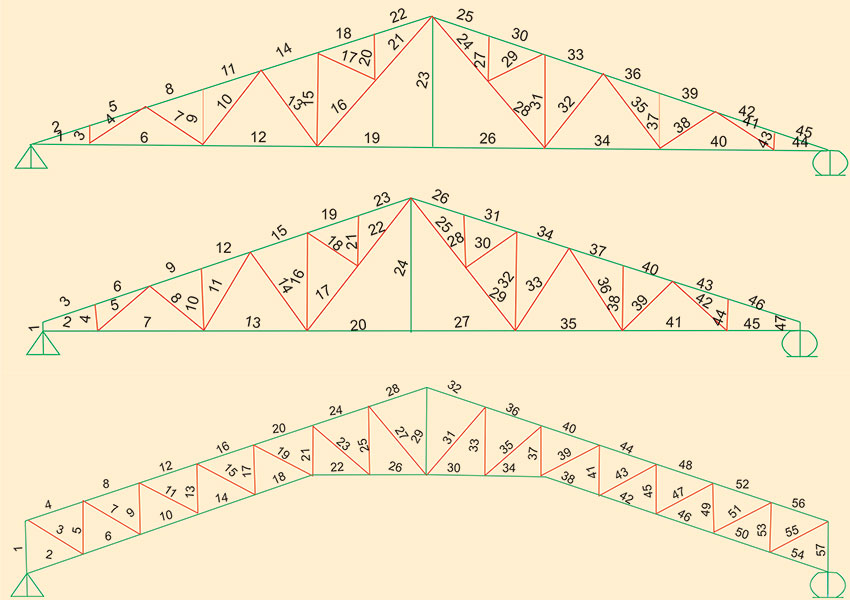
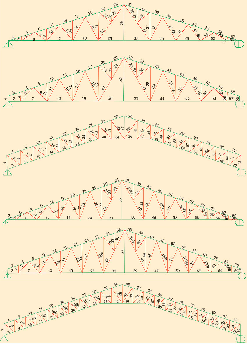
Triangular and triangular arch trusses are commonly used in a variety of truss roofed structures; these configurations of steel roof trusses with three different spans are investigated. The truss profiles of different spans varying from 20m to 30m are illustrated in Fig 1, Fig 2 and Fig 3. The spacing of trusses adopted in this study is at 6m centre to centre. Truss top chord slope, is 1 in 3 and the corresponding top chord angle is 18.4° in all the trusses. The parallel distance between the chords in arch triangular truss is 1.5 m for 25 m and 30 m spans and 1.25 m for 20 m span.
The analysis and design is performed using SAP2000 programme, and the code followed is IS 800-1984. However, the permitted increase in allowable stress by 33% due to wind is not implemented. The total truss is analysed assigning hinge support at one end and roller support at the other end. Support conditions chosen for the trusses reflect the actual situation of seating of the truss in practice, on the columns that are generally flexible. The truss elements between the joints are treated as rigid and capable of transferring moment and shear in addition to membrane force. Top and bottom chord members are designed for their respective forces optimally; similarly diagonal and vertical members are designed individually. However, one method in normal practice is to adopt a uniform section throughout the chord length in the top and bottom chords. But in the present investigation each member in the chord is designed for the level of its force in the top and bottom chords.
Loads on the Truss
The various loads the truss is subjected to are- Dead load
- Live load
- Wind load
Dead Load
Dead load on the truss includes self weight of truss, purlins, truss wind bracing, false ceiling and roof sheeting.With the input of these details of truss members in the programme, the self weight of the truss is automatically taken into account in the analysis by computer programme SAP 2000. The weight of roof sheet, purlins, and other services are fed in the analysis as input data at 0.15 kN/m2.
Live Load
As per IS 875-1987, the live load depends on the slope angle of truss top chord. For the slope of 18.4° in the present case, the live load works out as 0.582 kN/m2.Wind Load
The wind pressure is taken as 2 kN/m2. External wind pressure acting on the top chord on the windward side works out to -0.5256 P (from tables of IS 875 (Part III)-1987). On the leeward side, the pressure is - 0.4 P, where P is 2 kN/m2; ignoring the increased wind pressure in the corner and edges. Internal wind pressure depends on the permeability of the structure. It is taken here as ±0.5 P, assuming 5 to 20 % of wall area as opening area.Earthquake Load
Action of earthquake forces on the truss is not considered.Triangular Truss
Triangular truss is the most frequently used one, since antiquity. Top and bottom chords resist the moment coming on the truss at every section along the span, and the diagonal and vertical members in the web resist shear force. The slope of the top chord normally used, is in the range of 1:3 to 1:5. Higher slope 1:3 consumes less steel in the top and bottom chords and more steel in the vertical and the diagonals. As per the moment resistance requirement, the distance between the top and bottom chords is the maximum at the mid span where moment on the truss is the maximum. The only disadvantage is the zero lever arm distance between top and bottom chords at the supports. This invariably shoots up the forces in the top and bottom chords to higher levels, than those in the highest bending moment region, rendering the truss uneconomical if same member size is used throughout the bottom chord and similarly in the top chord. To remedy this situation, one vertical member of small height may be provided at both the supports, to lower forces in the vicinity of supports both in the top and bottom chords.Vertical and diagonal members of the truss provide the needed separation between top and bottom chords besides resisting the shear force at every section along the span. Inclination of diagonal members and the direction of external forces acting on the truss, decide the nature of force either as compression or tension in the diagonal members. Creation of tensile forces rather than compressive force is desirable in a slender steel member. For forces acting vertically downwards like dead and live loads in trusses, inclination of a diagonal towards the nearer support induces tensile force in it. In a truss, all external forces acting on it are not of same direction. While dead and live loads act vertically downwards, wind load generally acts perpendicular to the inclined top chord, the force is equivalent to large vertical force upward in direction and a horizontal force towards nearer support. The direction of vertical force due to wind is in opposite direction to that of dead and live load forces. This situation does not allow fixing diagonal inclination uniquely, however, if the designer is particular, the inclination can be decided depending on the direction of the higher vertical force, among the external vertical loads due to dead, live and wind.
The truss vertical supports are subjected to mainly vertical forces and small horizontal force which is equivalent to the difference of horizontal component of external inclined wind forces on the two top chords. Geometry of the truss does not create any horizontal force on the two supporting columns of the truss having triangular configuration.
Triangular Truss with Vertical Members at Supports
Vertical members are located on the supports with the only objective of reducing the forces in the top and bottom chords in the vicinity of supports. The resulting significant economy in top and bottom chords is slightly nullified by small increases in lengths of vertical and diagonal members. All other items applicable to triangular truss equally apply to this truss as well. The vertical members are kept at about 0.5m height arbitrarily. Increase in this height reduces chord forces in the triangular truss; at the same time, it increases lengths of the web members slightly.
Triangular Arch Truss
This truss is very commonly used in ware houses, storage sheds, industries for large storage space near ports. Triangular arch truss provides more storage space than a triangular truss below the bottom chord.
Availability of this space for storage is highly valuable for commercial purposes. The slope of the top chord in this truss also can be in the range of 1:5 to 1:3. The distance between top and bottom chord is part of design criteria. Obviously as the distance between the chords increases, the forces in the chords decrease. Based on a small analysis, it is qualitatively established that 20 % increase in the distance between the chords results in about 20% decrease in the chord forces. The slope of the both chords induces horizontal forces on the junction of truss bottom and column tops. The forces create moment in the support columns. Due to geometry of the truss, additional moments are induced in supporting columns unlike in the case of triangular truss. Columns in such structures ranging in height from 6 to 15m become more expensive than the columns under companion triangular trusses.
Supports to trusses are columns. These can be of structural steel or reinforced concrete. Reinforced concrete columns are maintenance free, cheaper, but more time consuming in construction than steel columns. The foundations for the columns depend on type of soil encountered. In sandy and gravely soils, cheaper shallow foundations can be adopted. In loose and marine clay soils, expensive deep foundations such as piles are needed. Under-reamed pile is the solution in black cotton soils. Cheaper wooden piles can be tried in place of expensive conventional reinforced concrete piles, for substantial economy.
Purlins and Roof Cover Sheet
Purlins
The only flexural members in trusses are purlins. Conventionally, purlins adopted are in mild steel with shapes such as, I beam, channels, angles (tubular sections are uneconomical when subjected to bending). Depending on purlin span, sag rods are used. For larger spans, built up steel sections such as triangular sections, used in railway platforms are economical. Currently, cold formed steel with yield stress ranging from 450 to 550 MPa is used in different shapes of sections such as C and Z. Use of this material reduces the weight of purlins, but increases the unit cost.Roof Sheet
Asbestos sheet commonly used in the past is now very rarely utilised because of health hazards. Currently, GALVALUME® metallic sheet is frequently used for roofing material. The unit weight of GALVALUME® sheet is far less than that of asbestos. Same material is used for cladding large truss roofed areas.Discussion of Results
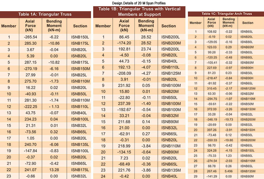
The trusses are designed with tubular sections having yield stress equal to 250 Mpa. Joinery of truss members is not touched in this study.SPAN: 20 m, Triangular Truss
The analysis is carried out separately for dead, live and wind loads. Dead and wind load combination yields highest forces in the members that have to be considered for member design. These forces are listed in Tables 1 through 3 for all the trusses and spans.The resulting member forces in the top and bottom chords depend on the geometry of the truss and influence the magnitude of forces. The distance between the top and bottom chords or the lever arm is the needed geometry. Due to near zero or very small lever arm, the forces in the top chord from support to quarter span are highest and nearly same despite lower bending moments. The forces keep on reducing up to centre of truss from the quarter span due to increasing lever arm. Same trend can be noticed in the bottom chord; adopting uniform section if needed in the top chord can be done, only with small economy loss. In the diagonals closest to the mid span maximum force occurs in the web. The total weight of the truss comes to 7.78 kN. The split of truss weight between various members is worked out. Both the chords weigh 6.60 kN and the web members weigh 1.18 kN which is 15.2 % of the total truss weight.
Triangular Truss with Vertical Members at Supports
There is slight variation in the geometry of the truss from triangular truss. It is only inclusion of vertical members at the supports, eliminating zero lever arm between top and bottom chords and creating some lever arm equal to newly placed vertical member height. The geometry change helps reduction in chord member forces, bringing closer to the forces in the remaining part of chord. Highest force in the chord member in the triangular truss with zero lever arm near the support 285.30 kN, has come down to 192.80 kN with the introduction of a short vertical member on the support. The forces in all the members in the top chord have become nearly equal, differing only by a small percent of 19. The bottom chord force distribution along the span is nearly same as that of top chord.As for forces in web members, maximum force occurs in the vertical member on the support. Forces in other verticals are small. In the diagonals maximum forces occur in the diagonal closest to the mid span of truss. The total weight of the truss comes to 7.66 kN while top and bottom chords contribute a weight of 6.13 kN, and the web members contribute a weight of 1.53 kN. The weight of web members is 20 % of the total weight of truss.
Triangular Arch Truss
In the triangular arch truss top and bottom chords are separated by a distance of 1.25m. Maximum force appears at quarter span from the support. From this location, the forces decrease more towards support than towards apex. The total weight of the truss is 8.68 kN. The maximum force in the bottom chord occurs at a distance of 1/4 th of span from the centre. The forces decrease to near zero value at the support. The decrease in forces towards mid span is small. The weights of top and bottom chords are 3.33 kN and 3.18 kN, respectively. The weight of web members is 2.17 kN which constitutes 25 % of total height of truss.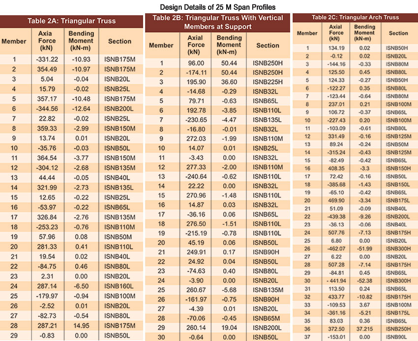
Comparison of Trusses, 20 m span
The total weight of truss is least at 7.66 kN for triangular truss with vertical member supports. Next higher truss is triangular truss with 1.6 % higher truss weight than the truss with vertical members at supports. Highest weight is recorded by arch truss. Arch truss is 11.6% higher than triangular truss in total weight and 13.4% higher than triangular truss with vertical members at support. Highest weight is consumed by chords in the triangular truss and lowest weight by triangular truss with vertical members at supports. While web members consume 25% total weight of truss in triangular arch truss, minimum weight of web members occurs in triangular truss (15% of total weight). The web members consume 20% of total weight in triangle truss with vertical members at supports. Overall maximum economy occurs in triangle truss with vertical members at supports. Maximum utility space occurs in the case of triangular arch truss with 11.6% higher weight than the conventional triangular truss.25m Span, Triangular Truss
With zero or near zero lever-arm at and in the vicinity of support respectively, the forces in the members close to support in the top chord are maximum in two-thirds of half-span from support. In the remaining one-third of half-span from truss centre, the forces are comparatively smaller (about 80% of maximum forces). Similarly, the magnitude of forces in the top chord is maximum in the three-fourth of half-span from support. Forces in both the chords are nearly same. While the weight of top chord members equals 5.22kN, the weight of bottom chord members is 4.6kN. The weight of top chord is slightly more than that of bottom chord. The total weight of web members is 3.52kN. The total weight of truss works out to 12.33kN. For 20m triangular truss, the weight of truss is 7.78kN. An increase of 5m in span increases the weight of truss by about 60%.Triangular Truss with Vertical Members at Support
In top chord, provision of vertical members at supports and consequent availability of some lever arm between chords reduce forces in the two members closest to support. However, forces in the remaining top chord members are similar to those of triangular truss. The total weight of the truss comes to 11.81kN. The weight of top chord members is 5.22kN. In the bottom chord the forces in the two end members in the half-span are small compared to those in the remaining members. The top chord and bottom chord exhibit nearly same magnitude of forces. The weight of bottom chord members is 4.6kN. In the verticals, the members at the support exhibit several times more force than in the remaining members. Moreover, diagonals closest to the support and the one closest to centre exhibit maximum forces. The weight of web members is 3.3kN, which is about 28% of the total truss weight. The weight increase in comparison with the companion 20m span truss is 4.15kN. It is observed that the weight of truss increases by 54% for a 5m increase in span.Triangular Arch Truss
The forces are maximum in the two members close to the support and one member close to the centre of span of the top chord. In the remaining members the forces are nearly same. The total weight of the truss is 14.40kN. The force variation in bottom chord members is nearly same as in the case of top chord. The weight of top chord and bottom chord are 4.88kN and 5.76kN, respectively. Vertical web members except one member at two-third of half span from the support exhibit nearly same force. In diagonals, maximum forces occur closest to the support and at truss centre. The weight of the web members is 3.74kN, which works out 26% of total weight of the truss. Total weight of this truss differs from the companion 20m span truss by 5.72kN. A 5m increase in span increases the weight of the truss by 66%.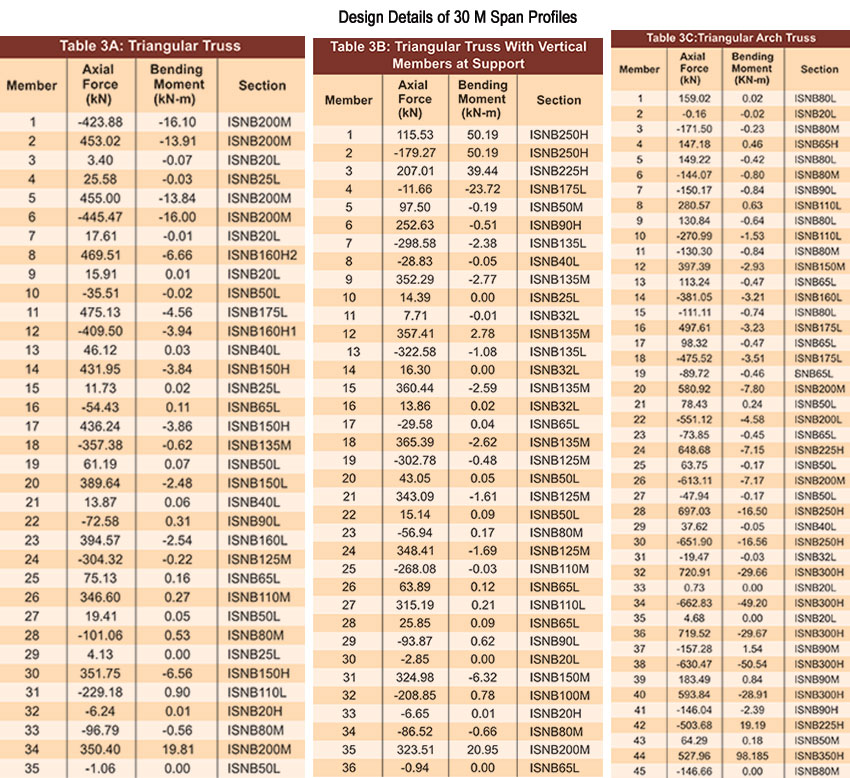
30m Span, Triangular Truss
30m truss is fairly on a big span. The variation in magnitude of forces in the top chord is within 16% in the first quarter span from support. However, the forces in the second quarter span are about 75% of those in first quarter span. Similarly, the maximum forces in the bottom chord occur in the first quarter span from the support. In addition, the forces in the second quarter span for bottom chord are about 85% of the maximum forces in the first quarter span. The total weight of truss comes to 17.52kN. The weight of top chord and bottom chord are 7.2kN and 6.1kN, respectively. In the web members, forces are minimum in first vertical nearest to the support and two verticals near the mid-span. The forces in the remaining members do not vary significantly. In the diagonals, the forces increase gradually from a minimum to a maximum value from support to mid-span, with small values in a couple of members. The weight of web members is 4.21kN which is 24% of total weight of truss. The weight of truss for this span increases by 125% and 42% compared to 20m and 25m spans, respectively.Triangular Truss with Verticals at Support
Incorporation of vertical members at supports, unlike in triangular truss facilitates the forces in the two or three members in the top chord nearest to the support to be reduced significantly in tune with the small bending moments near the supports. Also, in the bottom chord, two members nearest to the support and at centre, register minimum forces, because of smallest bending moment at the support and maximum lever arm, in spite of maximum bending moment at the centre of the span. The total weight of the truss works out to 17.18kN. The weights of top chord and bottom chord are 6.04kN and 5.18kN, respectively. In the web, the forces are maximum at support and minimum at centre of span for obvious reasons. Forces in the diagonal members are maximum at support and centre of span. In the other members, the forces are varying arbitrarily. The weight of web works out to 5.96kN, which is 35%of total weight of truss. This truss weight is 125% and 45% more than those of its companion 20m span and 25m span, respectively.Triangular Arch Truss
In the top chord members, the forces increase gradually from support to truss centre. The forces in bottom chord follow the same trend. The weights of top chord and bottom chord are 10.34kN and 8.62kN, respectively. In the web, the forces in the verticals gradually decrease up to quarter span and again increase up to mid-span of truss. The forces in the diagonals decrease from support to mid-span except in the two members closes to the mid-span of truss. The weight of web members is 4.55kN which is 19.3% of total weight of truss. This truss with 30m span weighs 170% and 57% more than its companion trusses of 20m span and 25m span, respectively.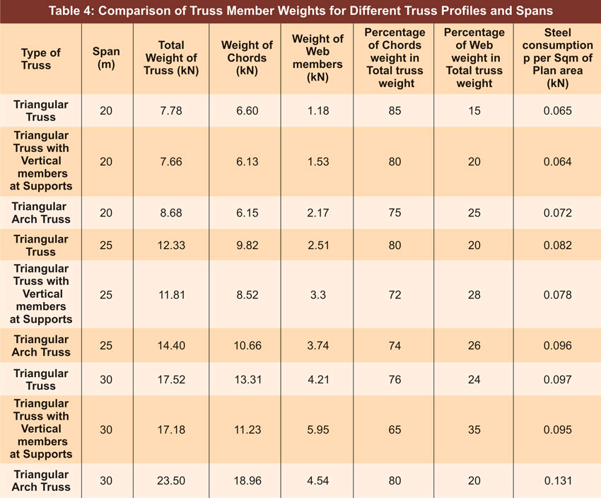
Table 4 illustrates comparison of truss member weighs for different truss profiles and spans
Conclusion
Based on the investigation undertaken, the following conclusions can be drawn for steel roof trusses. The items investigated relate to functional utility, total weight of truss and the resulting economy. Commonly used three types of trusses are studied. They are triangular truss, triangular truss with vertical members at supports and triangular arch truss.- Conventional triangular trusses are most suited with column free space to be used in auditoriums, cinema halls, function halls and large gathering areas facilitating provision of false ceiling and air-conditioning.
- Triangular trusses can be rendered more economical with the location of two vertical members of small height on the supports.
- Triangular arch truss affords more space below the bottom chord for storage purposes than both triangular truss and triangular truss with vertical members on supports.
- 1. For a given span, triangular truss with vertical members at the supports weighs least and triangular arch truss weights highest.
- Weights of web members in these trusses constitute 15 to 35% of total weight of truss in all truss profiles and spans; the highest percentage occurring in triangular trusses with the vertical members at supports, except in the lowest span, 20m.
- Steel consumption of trusses per sq. meter of built-up area of truss increases with the area covered by truss and varies from 0.064kN to 0.131kN for spans 20m to 30m.
- 1. Use of uniform section for the maximum force in the top and bottom chords instead of individual sections for the corresponding forces does not result in minimum amount of steel and economical advantage in a truss.
- Though purlins have not been part of the present study, in the total truss roof, the weight of steel purlins constitute a major percentage of truss weight and hence deserve special attention in their selection and adoption.


