Amit Bharana, President, ERA BUILDSYS Ltd.
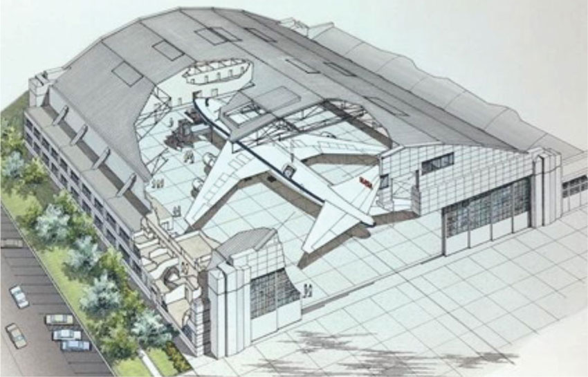
The majority of industrial buildings are made out of steel for obvious reasons of high strength/weight ratio. A study, on the Efficient Design of Large span hangars/structures, ensuring lighter foundations is presented.
Introduction

These days with the concept of PEB, the major advantage we get is the use of high strength steel plates (usually Fe 350), lighter but high strength cold form purlins, and 550 Mpa Galvalume profiled sheets. The use of PEB not only reduces the weight of the structure because high tensile steel grades are used but also ensures quality control of the structure. In the following study, we have designed a hangar using this modern concept of PEB.
Design Philosphy
The design under discussion is a 42 meter clear span hangar for aircrafts maintenance. We have designed this Hangar in 3D on STAAD software, for proper simulation of the load distribution uniformly in three co-ordinates system i.e. X, Y and Z. All the Basic loads i.e. Dead, Live, Wind, Temperature, seismic etc have been taken into consideration for designing of the frames. The structure has been designed under enclosed as well as open condition for application of wind loads, because of the opening & closing of the large sized Hangar Door.The basic philosophy of rigid frame design is by adopting ‘FIXED’ or ‘PINNED’ column base conditions. A fixed column base is always a sturdy frame and helps in controlling allowable deflection (side sway) in the frames. Steel designers always prefer fixed base to pinned base frames. On the contrary, for foundation designers the design of foundations becomes a nightmare particularly in large span buildings. In fixed base design, the frame is rigid, but transfers heavy moments to the foundations. On weak soil, designing foundations becomes tedious task. Likewise for pinned support, the frame does not transfer any moment to the foundation and only vertical & horizontal reactions affect the design of foundation. It looks simple but in case of large spans, controlling deflections of frame in pinned base condition is a challenging task.
To control this deflection, the simplest way is to increase the Geometrical properties/sectional sizes of frame, but it is not advisable as it adds to the tonnage of the whole building, adding not only to the seismic forces but also adding to the cost subsequently. We need a solution wherein the sway of the frame can be controlled and the section sizes are also not increased.
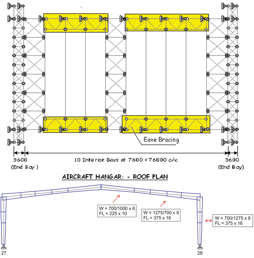
The best way we could find is to ‘BRACE’ the frame to control the excess deflection. In the present case we have provided bracing at eave level (braced eave) on both sides of the structure along the length for this purpose. Span of this Eave bracing is taken approximately L / 10 of each side. We can observe in the following example that eave bracing is of a great help in controlling Horizontal deflections and leading to lighter foundation design.
Example
To conclude above, as example hangar has done with following parameters having both side hangar doors with following details:| Span | = 42m |
| Length | = 76m |
| Bay Spacing | = 7.6m |
| Clear Ht. | = 10m |
| Wind Speed | = 50m/s |
| Roof Slope | = 1 in 10 |
Alternate 1 (Fixed Base Design)
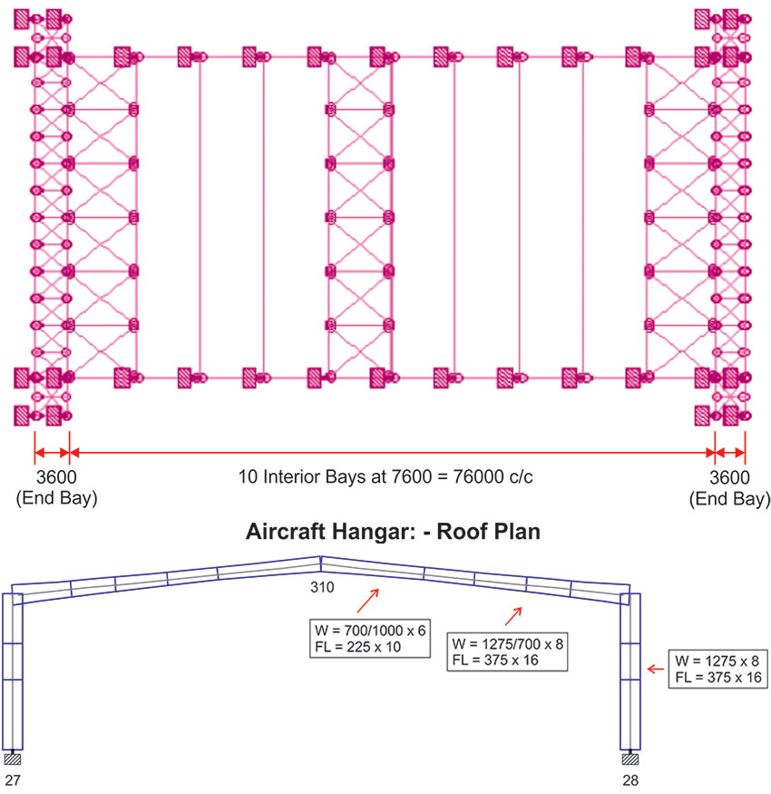
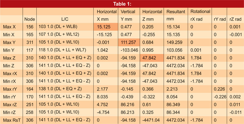
In fixed base, due of uniform moment distribution at base as well as eave, the straight column of section size Web = 1275 X 8 mm and Flange = 375 X 16 mm have been used. By using these dimensions of frame, the deflection is allowed in control. Please refer Table 1.
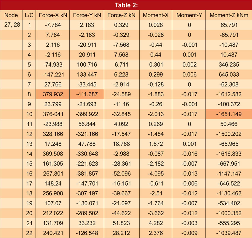
As regards foundation forces, the moment (Mz) is approximately 165 MT and vertical force (Fy) is 41 MT at the base of the column, which is being transferred to foundation. Please refer forces generated at base of frame in Table 2.
For above forces a tentative size of Isolated foundation is worked out as under -
Eccentricity (e)
e = (Mz/Vy) = (165 / 41) = 4.03
The length of the pedestrian (L/6) should be greater than eccentricity (e).
i.e. L/6 > e
L > 6e
L > 6 X 4.03 = 24.18 m ≈ 25 m (At Single Side)
Thus, it may be observed that the open foundation for this type of frame will be highly impractical & uneconomical and only solution is to provide pile foundation, which will again be time consuming & expansive.
Alternative 2 (Pinned Base design)
As second option, the same structure has designed with Pinned Base condition, now we can have tapered columns where moment (Mz) at the base will be ZERO. Only lateral (Fx) and vertical (Fy) forces will be acting. Please refer forces generated at base of frame in Table 3.
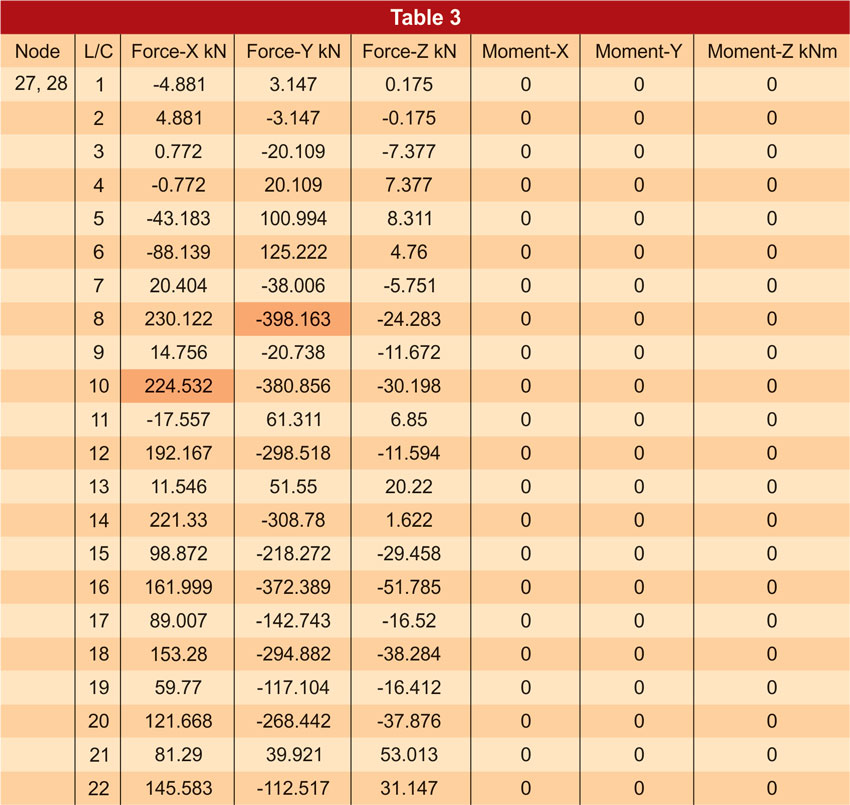
Due to zero moment we could design very light foundation (Sub-structure) for the same structure.
It may be observed that the foundation forces are very limited and a small isolated foundation can be design for the columns.
But at the same time, in pinned base, the deflections of the Portals in lateral as well as longitudinal direction will become critical parameter. And in case no special provision is made to control this deflection, the frame will have a considerable sway. Therefore for control of deflection, the provision of Eave Bracing (braced eave as highlighted) longitudinally on both sides of the structure has been made.
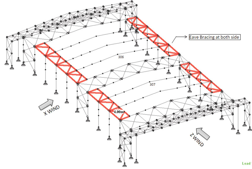
Span of this Eave bracing should be approximately span / 10 of each side. For 42 m span the width of eave bracing used 42/10 m = 4.2 m ≈ 4 m at each side (see below 3 D model)
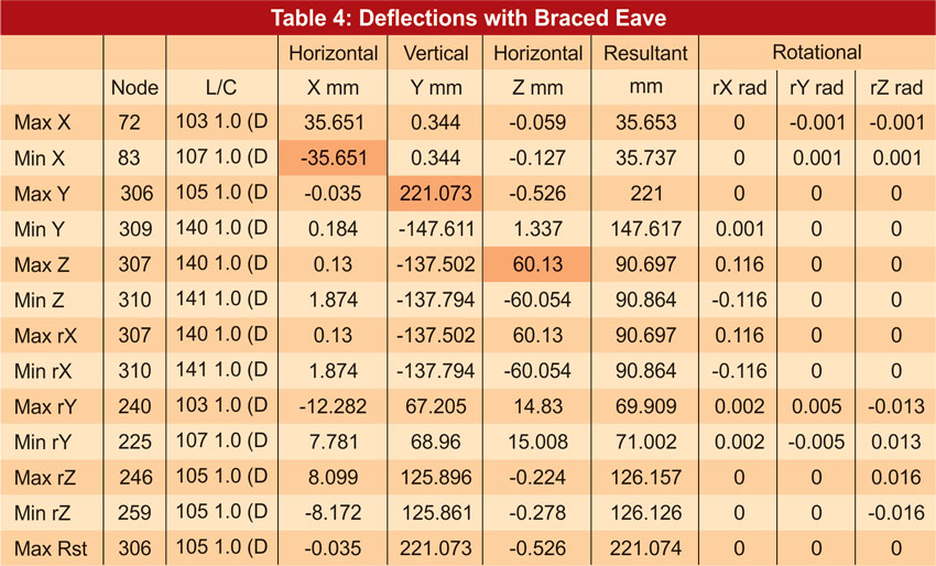
For comparison between the same sizes of frames with & without using the eave bracing, the deflection resulted in the framed are given in Table 4 and 5.
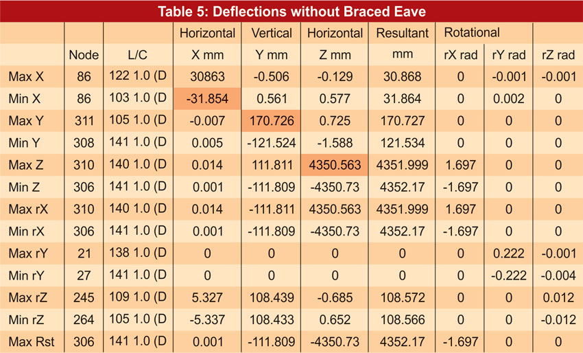
As per codal provisions, deflection allowed in columns is (H/150) that is 66 mm. In case of braced eave structure, deflection value was under control with 60 mm in longitudinal direction, however at the same time, the value was much more than allowable deflection in case the eave bracing is not provided i.e. 7566 mm which is very high.
Thus Eave Bracing Concept is very beneficial in large span structures with pinned base concept and since no moment is transferred to base level, the design of foundation is also very economical.

