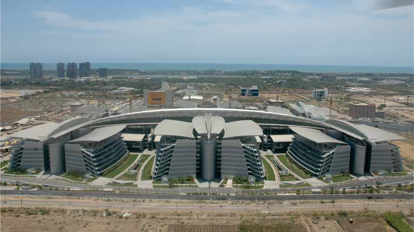
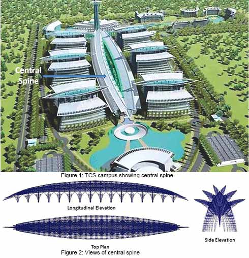
Tata Consultancy Services (TCS) India is building a new $200 million IT Park in Siruseri, Chennai. Designed by Uruguayan architectural firm Carlos Ott Architects in association with Carlos Ponce de León Architects, the project stands as an iconic development in the cyber corridor, distinct in the style, grandeur and aesthetics. Being truly an engineering and architectural marvel, the Techno Park is unique in the way it blends both business and lifestyle statements. It combines elements of traditional Indian architecture with modern design. An aerial view of the complex resembles six butterfly wings intertwined with a central spine.
The campus comprises a total of 12 buildings with varying height featuring five storeys in eight buildings and seven storeys in five buildings. All of these 12 buildings will be divided across the central spine that is 400m long and 42m high, with six on each side. Each block has two wings connected through bridges leading to the two central core structures which house the elevator lobby. The two wings and the cores structures are covered with expansive multiple three-dimensional umbrella structures. With water bodies, palm trees and, landscaping, this central spine is designed as an area for relaxation. At one end of the central spine, an executive and customer briefing block is featured, with a towering structure rising from within. At 130m, the tower will be the highest in southern India providing panoramic views of the zone.
Intelligently-designed, eco- friendly developed, this innovative design demonstrates environment-friendly processes, techniques and systems to meet the requisites for energy-efficient buildings, ISO 14001 certifications, zero waist disposals, carbon footprint offset, etc. The complex is notable for its microclimate performance based on an open atrium office buildings, providing a naturally-ventilated system. An ecological stream beneath a large overhanging canopy of 400m provides a natural cooling system. The Campus has already applied for Leadership in Energy & Environmental Design (LEED) Certification for Platinum and Gold ratings from the US Green Building Council.
Here in this article, we are presenting a case study on the evolution of the structural system of this project, discussing in particular the analysis and design of the central spine which resembles a 'Giant Wasp.' The paper will also discuss the structural system suitably provided for the huge cantilevers at the ends representing the tail, huge cantilevers at the sides representing the legs and the pyramid shaped lattice girders representing the body of so called giant wasp. Also will discuss about the behavior of central spine structure due to wind here.
Effects of Wind on A3 Dimensional Steel Structure for the Central Corridor Roof
The techno park at Siruseri, Chennai has 6 engineering blocks, customer care center, General services block, Training and library block and other facilities (Figure 1).The central corridor roof between the engineering blocks which is known as the central spine serves as the shelter for people movement. This also houses the landscape which consists of water body and other facilities. The architectural concept is such that 2 giant wasps each of 8 pairs of legs and long tails are facing each other. The formation of the entire structure is by means of 3 dimensional curves. In both the side elevations, it is symmetrical about vertical axis (Figure 2). In top plan, it is symmetrical about both vertical and horizontal axes as in Figure 2.
| Project team |
| Architect: Carlos Ott Architects in association with Carlos Ponce de León Architects (Uruguay, South America); Resident architect: CRN architects (Chennai, India); Engineering Services: Potential Service Consultants (Bangalore, India); Review and Project Management Consultants: TCE Consulting Engineers (Bangalore, India) |
Structural System
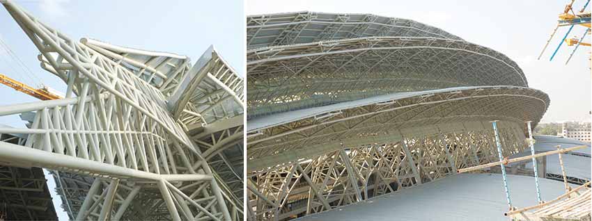
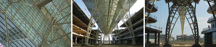
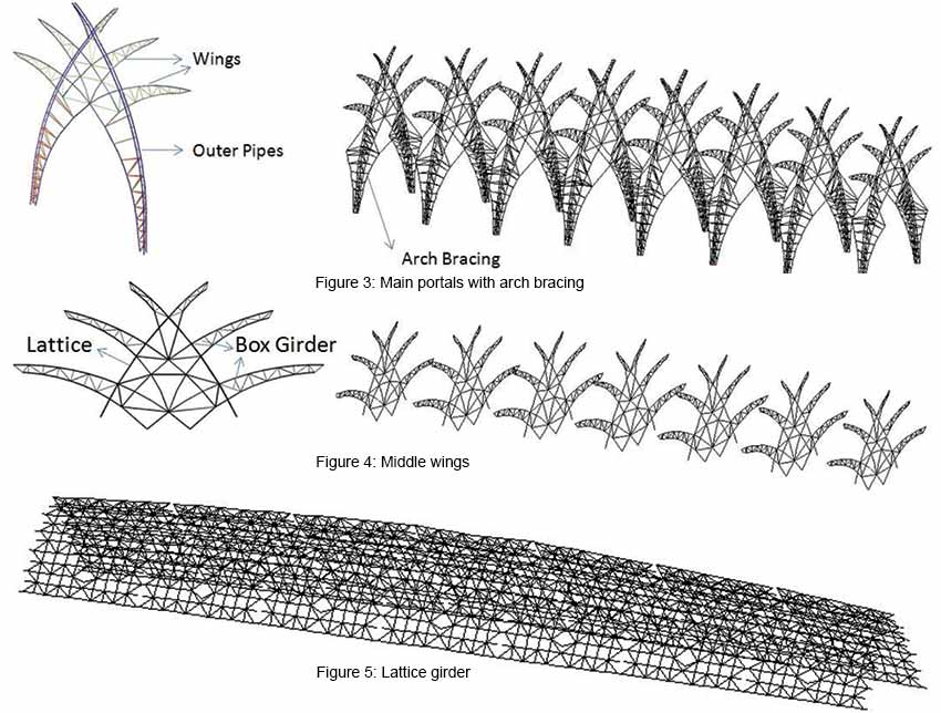
Main portals are formed by intersecting gothic arches (Figure 3). They are the main supporting elements of the central spine in the vertical direction. They are made of two outer pipes and one inner pipe as shown in Figure 3. These 3 pipes are connected by triangulated web members. They are further connected to the arch bracing members which are provided along the elevation. The outer and inner pipes form cantilever trusses called wings to support the purlins on them.
Middle wings
To reduce the span of purlins a truss system known as middle wings (Figure 4.) which are quite similar to the top part of main portals, are introduced in between the 2 portals. By this, the span of purlins is reduced to around 11 m which is reasonable. The middle wings are supported by the lattice and box girders running between the 2 main portals.
Lattice girder and Tail
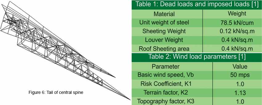
The lattice girder as shown in Figure 5 connects the main portals in the longitudinal direction. Between 2 consecutive main portals, at the centre it supports the middle wing. The lattice girder is connected at the bottom exactly at the centre to the arch bracing in each span. It is extended from the base of top wing to the bottom wing forming a curved pyramid. Tail is the continuation of lattice girder at both ends converging at a point. Space frame method is used to form this structure (Figure 6). It is an open structure without any roof covering, making it very obvious so that it looks like the tail of the "Giant Wasp." The cantilever is about 35 m from the last portal. It is tied back to the 2nd portal to control the deflection in the vertical direction and horizontal "X" bracings are provided at the bottom to control deflection due to wind.
Foundation
The two legs of each portal consisting of five pipes (including the arch bracing) are connected to a base plate with required stiffeners. Base plate is further connected to the podium column capital by means of cast-in holding down bolts.
Analysis and Design Data
LoadsDead loads and imposed loads have included the weight of all structural and architectural components on the basis of the unit weights as mentioned in the Table 1. Wind loads are based on the code provisions mentioned in IS 875 [1]. The wind speed is calculated using the parameters in Table 2.
Temperature loads and expansion joints
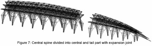
Elongation due to differential temperature is of high importance in long steel buildings. It can be taken care of by either providing expansion joints at an appropriate spacing or designing structural members for the additional moments caused by the temperature. Expansion gap between two structures shall be sufficient to accommodate temperature and shrinkage for effects due to wind. Expansion joints are provided at 2 locations along the length, breaking the whole structure into 3 parts known as Central part (1. no.) and Tail part (2. no.). Central part will have 7 spans. The final configuration of the whole structure is shown in the Figure 7.
Structural steel confirming to IS: 2062 with minimum yield strength of 310 N/sq.mm is used for all structural members. For expansion joints approved Teflon sheet is provided.
Wind Pressure Computations
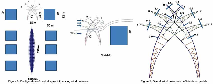
ConfigurationFigure 8 shows the configuration of the central spine (CS) structure. There are sixteen bays of geometrically similar configuration of diminishing size from centre to ends. Each bay is around 21 m long. At the middle, the width is 35 m and height is 55 m, at the ends the width is 12 m and 18 m height.
The bays are open in the bottom, for example up to a height of 24 m at the centre, above which CS supports six wings symmetrically by the framework, which also supports Louvers (water barrier made of overlapping plates) at the roots of the wings with a porosity of 20%. The Louvers extend below F&L.
Types of wind loads
The following cases have been considered to analyze the structure:
Case 1: Wind from empty position of A to B
Case 2: Wind from the direction of B to A, with A absent.
Wind loads with CS and building B only, wind from position A to B
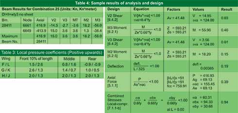
As shown in sketch 2 of Figure 8, the part of the wind below the point C will move on to B, gets diverted upwards and impacts to rear wing L. But wings K&L are partially shielded by F, G, H and their loads will be less than those values on G&H. Somewhat similar phenomenon occurs on the bottom of F, where the Louvers below F block the flow partially, creating a positive pressure. The Louvers between F&G and G&H also create positive pressure (or makes negative pressure, less so). The nearest configuration in the Indian wind code IS 875-1987 is Table 8 [1] for the wings F, G and H, J, K and L all with j=1. By considering shielding effect and the pressure build ups, the overall pressure coefficients with directions for all the wings and the Louvers are as in Figure 9. The configurations of Table 13 [1] and Table 14 [1] can be used as guidance with q=00. These are used for the analysis of the entire structure. The local pressure coefficients listed in table 3 are used for designing the purlins.
Wind loads with CS and building B only, wind from position B to A
Here, the bottom of wing L is above the building B and hence the flow will be similar to that as wing F with wind from A to B. Loads on K&J will be similar to those on G&H of the earlier case. However since F, G and H are fully shielded by L, K and J their loads will be half of the previous values including those on Louvers.
Structural Analysis and Design
Design of structural steel members is done using elastic method as per IS: 800 [2] with relevant allowable stresses. Each member is designed for combined stresses due to axial force, shear force and moments. Sample output for the analysis and design are shown in Table 4.
Conclusion
It is observed that the load combinations involving the wind loads computed using the pressure coefficients shown in figure 9 govern the design of members of the central spine structure. Since the structure is very light, the earthquake forces do not have any influence on the design. For academic purpose, the load combinations including earthquake, wind loads on members, live and dead loads are studied. The deflected shapes of the main portals with some governing load combinations are shown in Figures 10 and 11.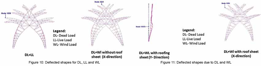
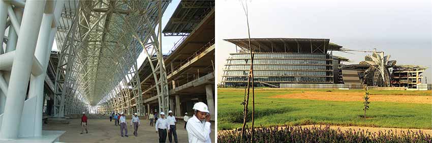
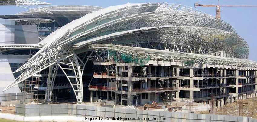
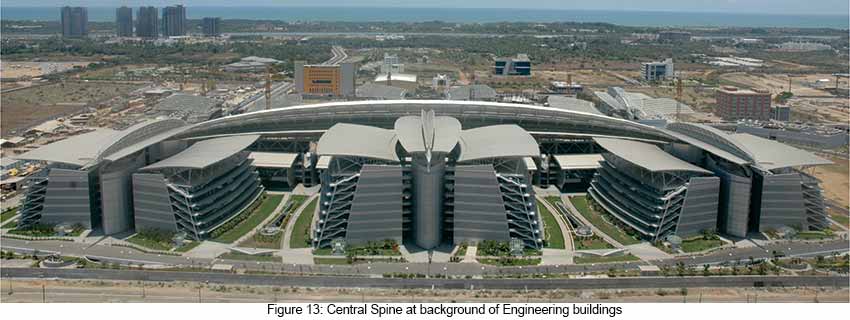
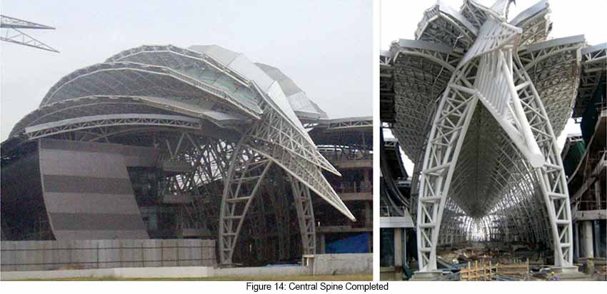
The pipe sizes used for the main portals are 350 mm diameter with thicknesses varying from 22 mm to 16 mm. For the other elements almost all available pipe sizes are used considering the most economical sizes and durability. The joints are connected by full strength butt welds. The thickness of base plate worked out to be between 70 to 80 mm for various portals by suitably providing the stiffener plates. Overall structural steel consumption is around 3000 Tons with a roof sheeting area of around 25,000 square meters. The central spine structure under construction is shown in Figure 12. Completed structure is shown in Figures 13 and 14.
Acknowledgment
The authors would like to thank structural engineers Mr. B. N. Sridhara, Mr. Sajeev Thomas and Prof. G. N. V. Rao, Department of Aerospace Engineering, Indian Institute of Science, Bangalore for their support and cooperation during the design stage. Authors are also thankful to the project team and clients Tata Consultancy Services Ltd for their cooperation in preparing this paper.
References
- IS: 875 (Part 1, 2 and 3) – 1987, Indian Standard- code of practice for design loads (other than Earthquake) for buildings and structures, Bureau of Indian Standards, New Delhi, 1989
- IS: 800 – 1984, Indian Standard- code of practice for steel design, Bureau of Indian Standards, New Delhi, 2002
Acknowledgement
The paper has been reproduced from the proceedings of SDSS 2010 (Stability and Ductility of Steel Structures 2010) with the kind permission from the organizers.T. S. Gururaj, Technical Advisor, Bangalore, India. Ex. President, Potential Service Consultants Pvt. Ltd., Bangalore
Nagaraja M. Thontalapura, Director – Technical, Innotech Engineering Consult Pvt. Ltd. Bangalore., Ex. Vice President (Civil/Structural), CPG Consultants India Pvt. Ltd., Bangalore


