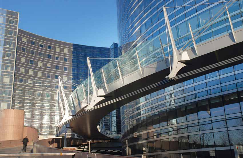
Linking the west part of the Parisian financial district La Defense with the city of Nanterre via the recently erected highrise building "Tour Granite", this 90m long footbridge winding through a dense architectural tissue is a modern urban promenade based on an ambitious structural concept.
The client – EPA Seine Arche – is an institution in charge of developing the public space between La Défense and Nanterre. During an architectural competition in Paris, the project of the architect Dietmar Feichtinger has been chosen. Dietmar Feichtinger is also an architect of the Simone de Beauvoir footbridge in Paris and the 3 countries bridge in Huningue. For the Valmy footbridge he was assisted by the engineers Schlaich, Bergermann und Partner (Stuttgart).
A suspended architecture between the buildings of La Défense
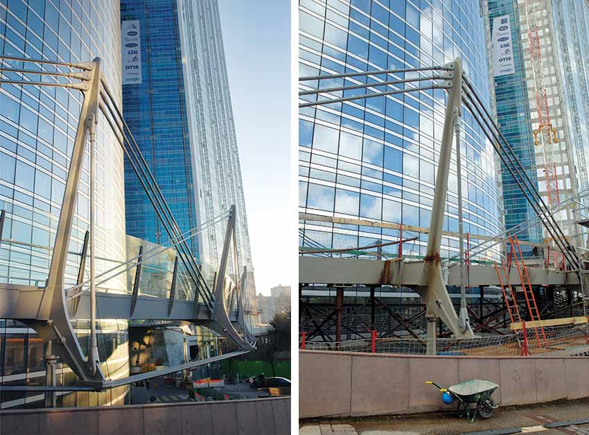
Starting off behind the Grande Arche as a ramp continuing the general level, the generous circumscription of the office building of the Société Générale Bank - visible in plan - asked for a specific solution. The architectural ambition for lightness and transparency is obtained by a balance of forces. The structural functions – tension and compression are clearly expressed. The dimension of each element is minimized. The organic and soft shape of the structure – close to the pedestrians – is in opposition to the monumental scale and the "cold" abstract expression of the highrise buildings.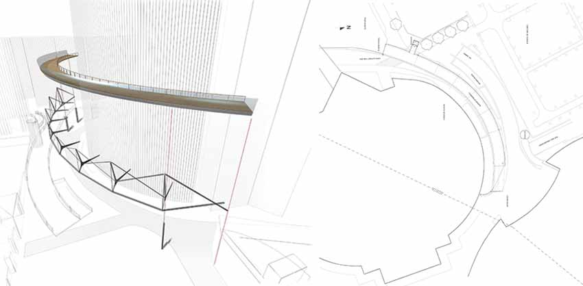
The bridge keeps a large distance with the building and the supporting structure has been transferred to the exterior curve. This allows obtaining a maximum of natural light for the offices and the cafeteria. The bridge attains the "Tour Granite" on the first floor. Escalators and stairs link up with the ground level in the city of Nanterre.
The rhythm of the structural elements assures the identity of the bridge. The main structural elements are the girders accentuating the bridge every 10 m as the "spinal column" of the bridge. The deck consists of a steel sheet box girder. The radiating "spine elements" are interconnected by pre-stressed cables. A system of cantilevers takes on the vertical forces. Resistance against torsion is assured by the deck and retaining cables below pre-stressed in the circumferential direction. The walking surface of the deck is covered with a uniform dark grey epoxy resin. The continuous surface opposes the stone pattern of the existing platforms and reinforces the impression of the bridge as a link.
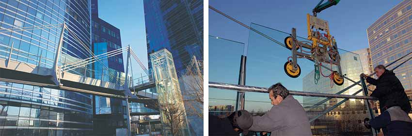
The railings are composed of pre stressed horizontal steel cables and a tube of stainless steel as handrail. The posts are made of 2 parallel steel plates including fixation for the light. Functional light is assured by fluorescent tubes vertically installed with each post and covered by a perforated stainless steel protection sheet. Glass screens as wind shields are fixed at the exterior curve so that the pedestrian may contemplate the cityscape. At night the illumination of the masts emphasizes the rhythmic structure of the promenade.
Structural Design
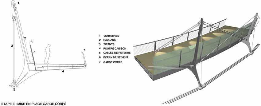
One can compare the structure of the Granite-footbridge with a spinal column: each element participates actively to assure stability creating a balance of tension and compression forces achieving maximum lightness: the spinal elements ("masts"), cables and the bridge deck.
The deck is formed by a steel beam, an element forming a trapeze in section - 4,5m large, 600mm high on the exterior and 300mm high on the interior edge. The beam is composed by welded steel plates, S355, reinforced with transversal stiffeners.
The spinal elements are made of steel plates, S460. They are oriented towards the center of the curved geometry of the deck. The main plates are stiffened by perpendicular plates welded to the main plate forming a cross section responding to compression forces.
The diagonal suspension cables link the spinal elements to the deck. All three elements compose the "spinal column" of the bridge. The retaining cables are anchored to the deck at the two ends. 3 monotoron cables of a diameter of 65mm are fixed to the spinal elements under the bridge deck. Prestress is induced during the mounting process.
Supporting Elements
The bridge is supported on each end by a combination of 2 anchoring elements fixing the beam: On one side the bridge is supported by a pile and anchored in the concrete slab of the existing platform, on the other side it is supported by 2 piles.The suspension structure – spinal elements and suspension cables – supports the vertical forces. It is positioned asymmetrically to the deck beam. Forces are being transmitted from the centre to the anchorage on the 2 ends. The closer one gets to the supports the stronger are the forces in the cables. This is why the number and the diameter of the cables as well as the height and the cross section of the spinal elements increase towards the supports.
Torsion is created by the curved geometry in plan and the asymmetrical layout of the supporting structure. Retaining cables are being installed under the bridge deck linking the spinal elements to balance torsion inducing a horizontal force. The curved layout and the inclination of the upper part of the spinal element demand transversal stabilisation. A vertical cable linking the two ends of each spinal element responds to this effort.
The bridge deck is as light as possible and responds to flexion and torsion. A lift gives additional access to the bridge linking the street level to the deck.
| Project Details | |
| Project | : Footbridge Valmy |
| Location | : France |
| Client | : EPA Seine Arche |
| Architect | : Dietar Feichtinger Architectes (DFA) |
| Team | : Christian Wittmeir, Guy Deshayes |
| Engineers | : SBP, Stuttgart |
| Aerodynamic studies | : PSP Aachen |
| Contractors | : Steel construction : VIRY SA |
| Fondations GTM | |
| Pre-stressing Electricity : Meurant | |
| Size and main features | : Length |
| Total length 90m | |
| Length without ramp Valmy 78m | |
| Clear Span 48m | |
| Width 4,5 m | |
| Weight | |
| Steel Construction 300t | |
| Reinforced Concrete 35m3 | |
| Excavation on Site 26m3 | |
| Tension Elements | |
| Tension rods 302m | |
| Section of Tension Rods 36~90mm | |
| Ring Cable / Cables 3x 75 m | |
| Strength of ropes 65 mm | |
| Height above street level 6 - 8 m | |
| Wind Screen (curved glass) 141m2 | |
| Time Schedule | |
| Competition | : 12/2003 |
| Start of Planning | : 2004 |
| Start of Construction | : 2006 |
| Completion | : July 2008 |
| Building Costs | : 2.8 Million € |
| Photo Credit | : Antonin Chaix |
Bridge Mounting
The bridge deck is composed by 26 prefabricated elements delivered on site by special transport. The elements are installed during the night on a temporary support, keeping the street on ground level accessible all time. The deck elements are positioned taking into account a counter curvature and welded one to the other obtaining a 90m long continuous deck.
The deck is positioned on temporary supports allowing readjustment of the geometry necessary due to deformation during the welding process.
Tension elements – suspension cables and retaining cables – are fixed on the spinal elements with connectors inducing tension and prestress. The retaining cables are tensioned by pulling the preinstalled cables towards the exterior curve. Special adaptors are fabricated to allow a step-by-step process. Jacks pull the cables into their final position. After positioning the retaining cables, the temporary support can by dismounted. The bridge takes its final structural state.
